Ok before I start I gotta give a huge NERD WARNING, as this stuff is probably going to be of not much interest to virtually anyone. Except all 3 people building a LiFePO4 on their boat. So, sorry about that.
That having been said, let’s begin! (references are at the end of the post)
Gudge currently has 2 deep cycle 110AH batteries connected in parallel for 220AH and a smaller starting battery, for a total of 3 lead acid batteries. Lead acid batteries are cheap, and last a reasonably long time. That’s about where the advantages stop – they are extremely heavy, vent dangerous gases when charged, can only be drawn down to around 50% without wrecking them and have a wonderful tendency to throw sulfuric acid everywhere in a knockdown situation. So not ideal.
Other types like AGMs and Gel batteries were basically fancy LA batteries, with slightly less disadvantages and an increased price tag. Lithium tech is different though.
LiFePO4 batteries (which are not the same type that blew up phones and nearly set the Boeing Dreamliners on fire) are about a 1/3 of the weight, smaller, don’t vent, can be drawn down to 20% safely and don’t throw acid everywhere. Which is always a plus. The disadvantages are cost, and the fact that a DIY setup involves replacing/reprogramming ALL of your charge sources, and creating your own battery protection system – lithiums REALLY don’t like to be over/undercharged and that’s a sure way to reduce your expensive bank to nothing. So basically you have to be prepared to read a lot for a while and learn a lot about electronics. And then read a bunch more, as to protect the bank you have to install a BMS (battery monitoring/management system). There are not very many of these knocking around and they all require some amount of self assembly. I ended up going with a Orion BMS JR.
In addition I had to get some remote switch/relays, a couple of MOSFET transistors and a lot of ring crimps.
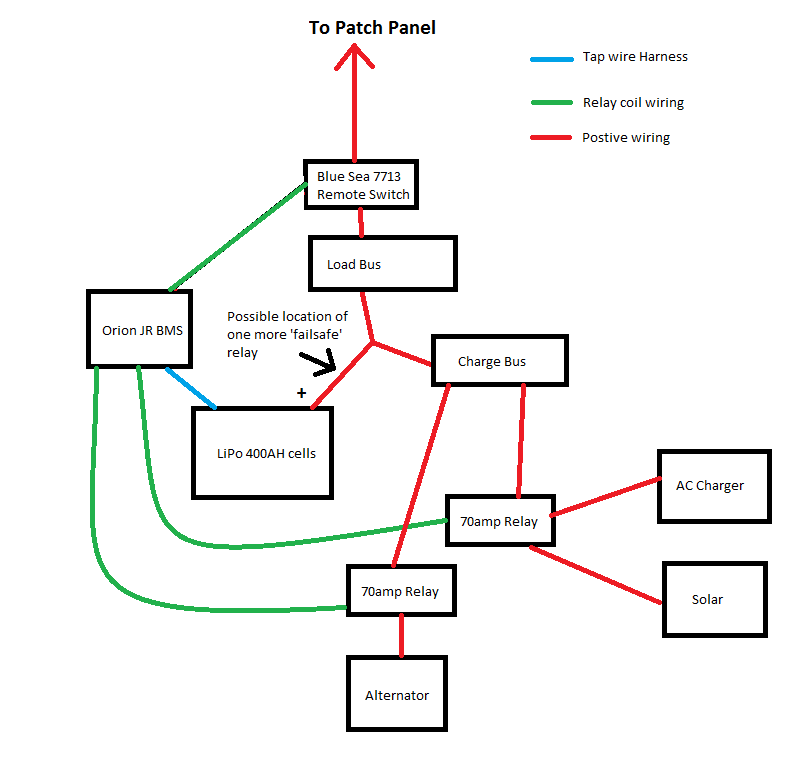
Here is the non-electrical-diagram-MSPaint-knockup of a very very simplified overview of the system.
Basically, the BMS monitors the battery voltage. If there is an over\under voltage condition the respective load/charge bus relay gets tripped by the BMS and the connection to the battery is broken. Same thing happens if the outside temperature drops (as you cannot charge lithium under 0 degrees).
This is a ‘last line of defense’ kind of thing – the alternator regulator, solar controller and AC charger will all be set to the correct voltage cutoffs, to avoid that situation. Unfortunately this means I have to replace the charger, replace the alternator/add an external regulator and reprogram the solar controller. Lots of time and money but that’s the rub if you want LifePO4.
I am also considering adding a final relay before the load/charge buses which is the total OH SHIT switch which will cut EVERYTHING off in case of a relay failure on the other buses.
This is just a really broad overview of the system – more to come! I bet y’all can’t wait.
Further Reading
Some really good articles are below
https://www.entropypool.de/2015/05/15/designing-a-lifepo4-battery-system-part-1-lifepo4-cells/
http://www.pbase.com/mainecruising/lifepo4_on_boats
http://nordkyndesign.com/electrical-design-for-a-marine-lithium-battery-bank/
http://honeynav.com/lfp-battery/

Very excited to read about the whole setup!
Thanks! May take a bit as I’m still puzzling over a couple of the details
Thanks for sharing Matt. Sounds pretty sweet! Did you use any breakers/fuses in your circuits?
Think I’ll go Li when my AGMs die.
Yup – I’m going to do a more detailed breakdown of each part of the system as I install it and will provide more details then. Short answer – everything is fused 🙂
Hello! I’ve been following your LiFePO4 build intently. Great work! I will be doing a similar setup, but in a sprinter van. Where did you source your batteries? I figure it would be a good be source me as well, since we’re both in Victoria.
Oh man, I didn’t actually mention that! I got them from Randy at Canadian Electric Vehicles – http://canev.com/
Local on the island so I just picked them up. He orders every 3 months or so in a big shipment. randy@canev.com
Amazing! I’ve totally heard of this company before. Just put in my order!