Now I had the mounting system, it was time to hook the lithium system up, including the LiFePO4 BMS.
WARNING: I know I do this a lot, but this entry is heavy on the technical details and light on everything else, including excitement, humour and ~fun sailing stuff~. Here we go!
The Batteries
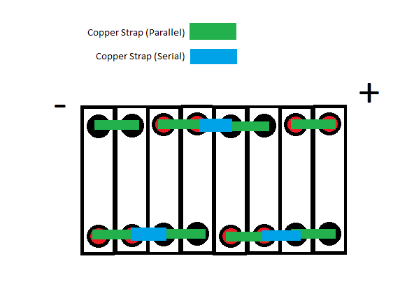
The cells were organised in a way called 2P4S – as in, pairs of batteries were connected in parallel and then these 4 groups were connected via series. Basically like this. I put them in the new space, secured them and then attached the copper busbars being VERY careful not to short them out. I wrapped a spanner in electricians tape to insulate it.
Connecting the Orion JR BMS
Now that the batteries were arranged in their final configuration (and mounted), it was time to connect the LiFePO4 BMS I was going to use to monitor the pack. A BMS basically keeps an eye on the cell voltages – if any start to go too high or low (indicating under/over charge) then the BMS drops a connection, breaking a relay and the charge/discharge stops. More info is in the first post of the series.
Connecting the cell taps
The cell tap connector looks like this
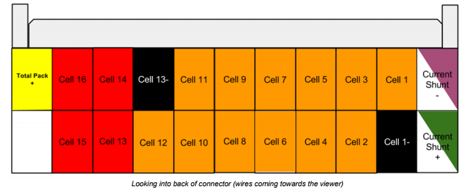
Yeah, that’s a lot of wires.
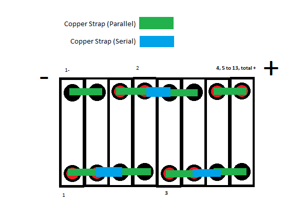
It’s actually two cell groups, 1-12 and 13-16. Since I just had 4 cells in series I could ignore the 13 to 16 leads and the 13- one. The current shunt leads attached to my current shunt, the cell 1- tape connected to the negative side of the battery, the cell 1 tap connected to the + side of the first (parallel) connected cell pair, cell tap 2 connected to the + side of the second cell parallel pair and etc for cell taps 3 and 4. Cell taps 5 – 12 all had to be connected to the positive of cell 4, as did the total pack+ tap. THAT’S A LOT OF WIRES.
Here is where all the taps went (the tiny numbers written next to the cells) (not shown – the current shunt ones as they went directly to shunt)
Connecting the other connector
Oh you thought that was it? Sadly not. Here is the OTHER connector, that controls all the relays etc
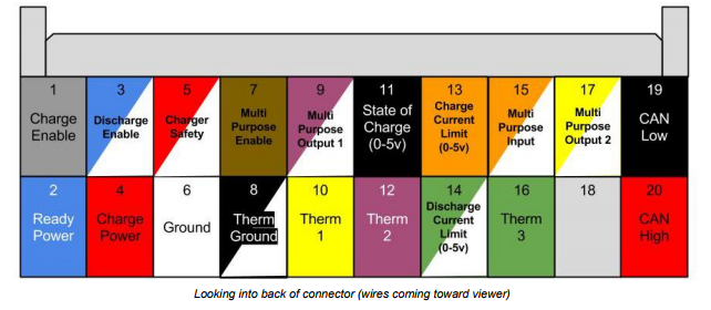
So it’s probably easiest if I go down through each pin in order. HOLD ONTO UR BUTTS
1 – When the BMS decides that the voltage etc of the battery is ok to allow it to charge, this pulls to ground. If there is an over voltage condition, it shuts off. Connected to a RA-700112-DN (70 amp relay) on pin 85.
2 – This is connected to +12Volts and turns on the BMS when connected. I connected it to a switch, and from there to the battery. This is the only thing directly connected to the battery (aside from voltage taps). Fused.
3 – This is the opposite of pin 1, in that it controls the discharge (i.e – stuff running off the battery). It actively pulls to ground, and if there is an error condition or an under-voltage condition (i.e I’ve used too much juice) then it switches off. Connected to a Blue Seas 7713 remote battery switch. Note: this switch requires a 12+ input so I had to do some extra fancy wiring (see below)
4 – Not used. More for electric vehicles to recognise when they are plugged in.
5 – Not used. Same as 4.
6 – Ground wire. Connected to ground. Pretty self explanatory.
7 – Now, this one actually ended up driving the main relay which was a Blue Seas 9012 (also known as the OH SHIT relay as it’s the last line of defense if the charge/discharge enable fails). This wire draws to ground like the others, and when it detects and under/over voltage condition it shuts off, shutting off the relay. This relay is IMMEDIATELY after the battery, and everything that draws power (aside from BMS) connects on the other side of it, isolating any charge/discharge source from the battery. It also is ‘watchdog backed’ meaning it turns off automatically if a BMS fault is discovered.
8 – Ground for the thermistors. Self explanatory. See also 10/12
9 – This basically has the same functions as 7 – it is an output pulling to ground that is configurable. However it is not watchdog backed, meaning I didn’t want to use it for any of the ‘main’ relays. This one I used as part of the state of charge display, it activates when an error is discovered and turns on an error LED.
10 – positive lead for thermistor 1. This measures the temperature around the batteries, as they shouldn’t be charged under zero degrees celsius.
11 – This wire uses a voltage between 0 and 5v to show state of charge of the pack. I ran it to a little SOC display so I didn’t have to plug in the laptop every time to see the SOC.
12 – Thermistor 2. See 10. Basically another one same as 10 so I have some redundancy with the temperature measuring.
13 – This uses a voltage between 0 and 5v to show the current limit. I run it to the SOC display to show if charging has been shut off.
14 – Same as 13 but for discharge. Not used.
15 – This can be used to do a couple of things. Not used.
16 – Same as 10 and 12. Not used.
17 – Same deal as 9, as in same as 7 not watchdog backed. I used this one to drive another RA-700112-DN relay that controlled the power to the alternator regulator. This was set to shut off slightly before the over-voltage protection on pin 1, meaning the alternator would shut off before the charge circuit is disconnected, which would otherwise damage the diodes.
18 – Blank
19/20 – leads for the canbus, which is a protocol that the BMS can use to talk to similarly equipped chargers etc. I don’t have any of these so it wasn’t used.
Relay Details
Main Relay
This is a Blue Sea Systems 9012 relay.
It’s sat between the battery and the main charge bus, meaning that EVERYTHING is on the other side of it. The only things that are powered not through the relay are the BMS (which will which to a low power mode drawing 0.1 watt if it detects a low voltage condition) and the positive of the 9012 relay coil. The negative of the relay coil is connected to the BMS, see above. Positive coil was fused and connected directly to battery.
Discharge Relay
This was a Blue Sea 7713 Remote Battery Switch. I used this instead of another 9012 as it used less power to keep engaged and also had a manual override, for when I REALLY needed that last 20% of battery. It sat between the main bus and the discharge bus (that had almost all the loads on it). In an under-voltage condition, the BMS stops pulling to ground on the control wire and the discharge bus shuts off. HOWEVER
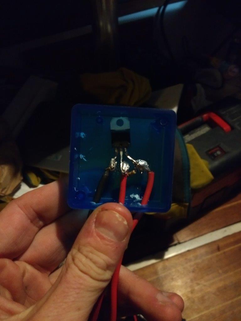
As mentioned above, it needed a +12v source, so I couldn’t just hook the BMS up to the negative coil side like the other relays. I used a P‐Channel MOSFET (STP10P6F6) and a 100k resistor to ‘invert’ the output from pulling down to ground to a +12v output. This was then mounted in a case. Wiring was as follows
Gate – attached to the discharge control wire from the BMS
Source – connected to the main charge bus (+12v)
Drain – connected to the +v side of the 7713 coil control wire.
100k resistor connected between source and gate.
Note shitty soldering job – after this photo was taken I got a little solder stand that made it way easier and I redid it a lot better – but forgot to take a photo. So here we are.
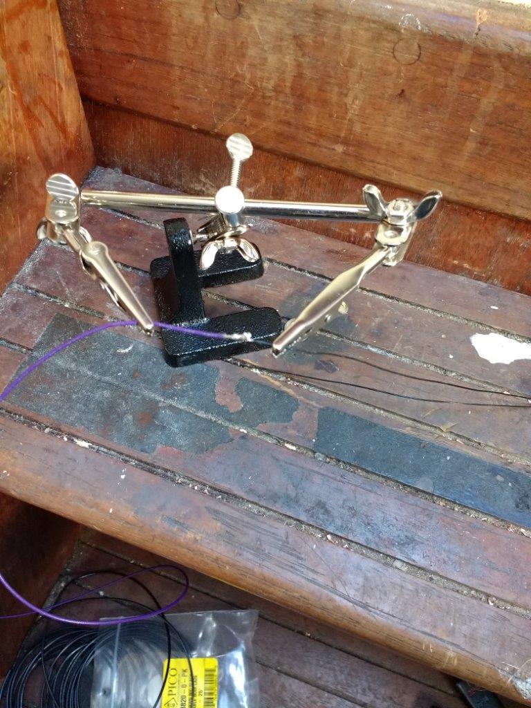
This is me using the stand to solder the thermistors. This was also annoying.
Once this was done, one main lug was connected to the main bus, the other was connected to the discharge bus, the +12v coil wire was connected to the drain of the MOSFET (and fused) and the ground coil wire was connected to ground.
Charge Relay
This was a RA-700112-DN 70A Relay that was connected before the charge bus that all my charging sources lead to. In an over-voltage condition, the BMS stops pulling to ground on the control wire and the bus switches off. Simple.
Except the connectors on the main contacts were this weird large tab that I couldn’t find any female connectors for so I ended up having to drill a hole and bolt on ring connectors to. Like below
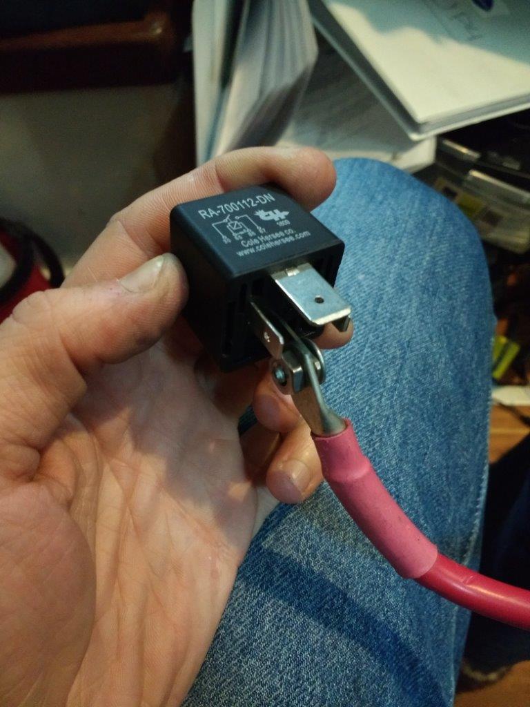
The other thing to note is that this relay has a diagram on the front which DOESN’T correspond to where the pins are. Pin 85 and 86 are on opposite sides compared to where they are on the diagram, so I ended up plugging them in reversed and blew a fuse. Oops. CORRECT wiring is as follows
Main pins
Pin 30 – Connection to main bus
Pin 87 – Connection to charge bus
Coil pins
Pin 85 – Connection to charge enable wire on BMS
Pin 86 – Connection to main bus (+v). Fused.
I kinda wish I had used the SPDT version (this one is a SPST) as I could have used the other throw to activate a buzzer that would sound an alarm if the charge level got too high. No matter!
Alternator Regulator Power Relay
Snappy title hey? This is the same RA-700112-DN 70A Relay that I used on the charge bus, complete with the same dumb tabs on the main contacts.
Main pins
Pin 30 – alternator regulator power wire
Pin 87 – 12v+ coming from ignition power circuit (so it turns on when the engine key is turned)
Coil pins
Pin 85 – Connection to multipurpose output 2 wire on BMS
Pin 86 – Connection to charge enable bus (+v). Fused.
The idea here is that the voltage settings for the Multipurpose Output 2 wire from the BMS are set slightly lower than the charge cutoff, so this relay will trip before the charge one does, killing power to the alternator regulator and hence stopping the alternator charging the batteries safely. If we just cut the charge bus without doing this first, you could damage alternator diodes.
Voltage Levels
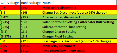
The various voltage levels at which stuff activates are above. Some of the stuff relies on cell voltages, other on pack voltages – I put both in to make for easy comparison, but the ones in brackets aren’t actually used, just included for reference. Aside from the stuff in green, all the red/yellow stuff is controlled by the LiFePO4 BMS and should (theoretically) never happen, as the other charging sources should always keep the voltages in the green.
You may notice the charger settings are SUPER low. This is so that the battery bank is kept between 30% – 40% charge (roughly), meaning I can leave it a week or two without worrying that I am destroying the batteries. The night or morning before I head out, I’ll bump the settings up to 13.8 so I’ll leave with a full charge.
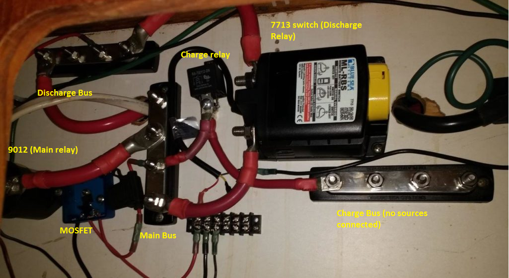
Other stuff
To provide an example of what this all looks like, here is around 70% of the system wired up. Note that none of the BMS wiring is in place yet, but you can see where it would attach on the relays and terminal blocks. You can just see the edge of the main ground bus on the right of the picture.
I mentioned the alternator regulator a few times but haven’t provided much details. That will be in a later post.
The LifePO4 BMS is programmed through software on a laptop that you connect into with a serial cable. The Orion JR BMS is pretty easy to configure, the only thing that confused me was the way you set the charge and discharge limits – its on the ‘cell settings’ tab. Everything else is done on the page for the actual output.
If you made it this far – congrats! And good luck with your own LifePO4 system!
I think all you are really doing is convincing us we are not smart enough to ever consider putting in lithium 🙂 I’m certainly terrified now.
Oh no! It’s not THAT complicated when you get stuck into it, it’s just a LOT of wiring. In the 18 months since I started planning for the project, Victron have realised a lithium battery and a BMS with integrated relays – which I imagine simplifies everything a 100 fold. These folks have just bought one https://schourup.net/2018/01/10/lithium-battery-setup-a-first-plan/
Dude, seriously, well done!! I’m happy you figure this out and got it working! Not going to have to worry about power for quite awhile. 🙂 I’ve been following closely, and now have a well laid out guide on how to build my own battery pack!
Thanks Gary! 🙂
Ok… all that has gone way over my head. Congrats on such a project!
But personally dropped my spanner on the my house battery poles while servicing it last year. It wasn’t stuck on for more that 2 seconds (I kicked it off!) and was burning hot for over 1/2 an hour! Lesson learned…. tape that mother!
Aaaaaa so scary! I heard tales of molten metal flying around etc!
I just looked at this and the first thing that sprang to my mind was why such a complicated system?
When you get hit with a monster storm (it’ll happen if you want to go sailing the world or not) and your first knock down (this will also happen), and something somewhere goes, (przzzzttt) followed by darkness (it’s always fekkin dark when stuff goes wrong), will be you be able to fix this with one hand, hanging on with the other hand and unable to see because it’s dark?
If a cell gets damaged, can you replace it easily anywhere in the world?
Hey. its LOOKS super complicated but most of the complexity is in the monitoring. I can easily override any of the relays/monitoring with a jumper cable between bus bars (that I already have made up) . The whole system is actually a lot more resistant to knockdowns than the old lead acid batteries I used to have – it’s inside, tightly locked down and won’t throw acid everywhere (a plus). Replacing cell isn’t easy, but the bank can be reconfigured around the damaged cell, though at a capacity reduction. This isn’t something you’d want to do in the dark though for sure.
Hi Matt,
Did you look at many other options for BMS’s? I know MainSail recommended this one in his LiFePO4 article, but the only very minor issue I see is with Multipurpose Output 2, since it is not watchdog backed. If a fault ever occurs while the alternator is running, everything (charge bus, load bus, main bus) will disconnect aside from the alternator regulator? Damaging the alternator? Correct me if I’m wrong.
Or are you just assuming faults are very rare and accepting the small risk?
Thanks,
Luke
Hey Luke,
I looked at a bunch, but since I bought the cells more options have come available – one that may be worth checking out is the Victron stuff. They now do a lithium battery + BMS that has integrated relays, simplifying a lot of stuff. A bit more expensive, but…
You are exactly right on the Output. It is a risk, but as I don’t tend to run the motor that often (being a sailboat!) its a really small risk, Worse case, I MAY damage the alternator diodes but still have charging from my solar (and I have my old alt I can put back in in a pinch).
Obviously for something like a van this becomes a lot less of an acceptable trade off… :). In that case maybe use the charge enable to cut the regulator power as well as the charge bus by duplicating the signal, but the charge bus has some sort of delay on it so it cuts out just after the alt reg does? Although that’s getting a bit beyond my electronics knowledge. Check out what some of the other links on this page have done re: alt.
Matt,
Read your articles several times… I’m putting together a 2p4s ca180fi set for 360ah, Orion Jr., Victron 12/3000/120 inv/chgr, 320w solar w/ Victron MPPT, Balmar 100amp & mc614. My question is that since my charger is potentially outputting 120amps, and the alternator max is just shy of 100, what relays should I be using for the HVC/LVC control? I’ve been shopping around for 120amp relays and I’m not sure what would be best?
Thanks for the help and the useful info,
Roark
Hi Roak, I haven’t actually looked into it for a long time (and was lucky enough to be able to use a 70amp one for my disconnects) so I can’t give you any specific models I’m afraid – maybe go to a website like https://www.mouser.com/ and you can search by ampage and all kinds of things. One thing you could do is use the blue seas 9012 relay as the general HVC control and then put the control wire for the balmar onto a seperate small relay controlled by a different wire from the Orion BMS? That’s similar to what I did, though I just used the 70 relays I had at hand – but it’d only have to be 20 amps or so. The solar and charger probably wouldn’t need seperate relays.
Hi Matt,
Thanks for the input. I did use 9012’s. After finally figuring out the Multi Purpose Enable (setting to Contactor!). My ‘main’ & ‘charge’ relays are functioning.
I have a question on the 7713: I did exactly as you did w/ the ‘mosfet-in-a-box’, and tested that when the BMS is turned on I have +13ish on source (right most wire), +13ish on drain (middle wire). I even put a meter on the red & black coil wires and they show +13. But, the 7713 doesn’t switch on? It works in manual mode.
I’m stumped. What am I missing?
Thanks,
Roark
Hey Roark, mine is kinda funny too (tbh I probably would use another 9012 now). It works fine – except the only way to get it to enable after the power is turned off and on to everything is to connect the laptop to the BMS and ‘send config’ – give it a try, making sure the switch is in the ‘auto on’ position
It’s something to do with the way the internal switch logic works re: turning on automatically.
Matt, Thank You!!! I thought I was going nuts :-), I’ll give it a try tomorrow and replace w/ a 9012 if I don’t like it.
Kk let me know!
Hi Matt! As you know I used a setup very similar to yours, I have 9012 everywhere and a 7713 uninstalled in a box somewhere on the boat (!)
Nathaniel from SV Poppycock is building up his system too and asked Orion about the 9012 which is basically the same specs as the kilovac ev200.. and Orion responded this:
“This contactor cannot be directly driven by the JR–you will need to use a signal level relay in conjunction with this (the BMS activates the signal relay which then engages power to the contactor). This is described in detail in the Orion JR wiring manual on page 22. Have you reviewed this resource yet?
Regarding your question about people who have seemingly used the JR to directly drive this contactor–it’s the kind of thing that might work under some circumstances, but it does exceed the max ratings for the product. Most likely this will not work reliably in all temperatures / voltages and may end up damaging the unit over longer periods of time.
Is it possible the other customers are using a 48v version of the contactor? 175mA might be sufficient to control one of these at 48vDC (the coil current goes down as the voltage goes up) but I am not sure offhand.”
Thinking of this now and since I do have a 48v bank as well I should have bought a 48v coil switch to be compliant.
One of my two JR was DOA when I came back to the boat a few months ago. I still don’t know what caused this and I need to send it back for autopsy. The new one I received is working perfectly now but I am installing opto in between all the ev200 to be on the safe side now.
I though it could be of interest to you and followers 🙂
Thanks for the update! I managed to resolve my issue by adding an extra switch between the switch and the MOSFET. More details here. https://www.gudgeonblog.ca/lifepo4-batteries-part-eight-adding-an-additional-switch-to-the-discharge-relay/
Hello Matt! Been using your article (along with MANY others) to put my system together. I am a big believer of the free propegation of knowledge and will be doing my part as well once I fully figured everything out. I am the “Nathaniel” mentioned by Patrick so I am also using the Orion Jr and want to use exclusivly 7713 (if possible). I think I have overcome the problem of the 7713/orion with a simple relay and would love to show you my schematic and see if you think it would work and then I’d be AOK if you wanted to publish it as well. I just realized now that I can’t send you a pic of my schematic. I have it posted on our FB page or I can email it to you directly.
Cheers, and happy sailing!
Hey,
Just took a look at your Facebook page. It looks like it should work – although I had to put an extra switch on the power side so I could manually cycle the switch after the main power on, something to do with the MOSFET powering up a bit slower than the switch I think? I’ve dropped a link to what I did above
Let me known if it works out – the 7713 is nice but adds more complexity over the 9012. My 9012 works just fine without needing the MOSFET.
PS – jealous of your alt charging capacity 🙂
Did you fuse any of your tap wires or are you going the route of using the 22awg wire as the “fuse”?
None of the tap wires were fused
I’ve been testing a setup similar to yours, and used your notes in conjunction with the docs to try to make sense of things. I’ve noticed that cell balancing doesn’t appear to turn on, I guess because the pin #4 in the I/O harness isn’t connected to anything. Have you noticed this as well?
I’m in the middle of load testing it all so I’ll check my hypothesis once that’s over, but I figured I’d ask you if you noticed cell balancing ever happening.
Also, to allow the BMS to re-enable the charge/discharge relays without having to connect your computer and send a config, you can add a setting in the Relay settings tab that will re-enable the relays after a period of time and if the SOC and current limits have improved.
hmm this posted as Anonymous, i’m not sure why
Relay Settings -> Charge Enable -> Allow relay to turn back on after X second(s) if:
(select a logic that fits you, I put “Charge current limit is above 100A”)
Relay Settings -> Discharge Enable -> Allow relay to turn back on after X second(s) if:
(select a logic that fits you: same stuff)
Hey
Yeah I had to connect the #4 pin to 12v (I wired it to the switch) in order for the auto cell balancing to work. I had this off for the longest time but decided on balance it’d probably be worth doing.
I had those relay settings set, but the my alt cut off was driven by the multipurpose relay which those settings don’t effect unfortunately – although I have since updated the firmware and it appears it actually may do now. I fixed the ‘needed a laptop to resend the config’ by adding a switch on the 7713 power side.