A quick update here – just to add an addendum to the LifePO4 series. No-one who is following this blog for travel reasons will find this interesting, but it’s an important point as I know several people use a 7713 as a main relay in their systems.
There was an annoying bug where if I turned off the battery bank and turned it on again, the discharge relay (a Blue Seas 7713) wouldn’t turn on, and I had to connect a laptop and do a soft reboot. This is because it was looking for 12+v on the switching wire – but for that to happen, the BMS had to power up first. Having both of them come up at the same time didn’t work.
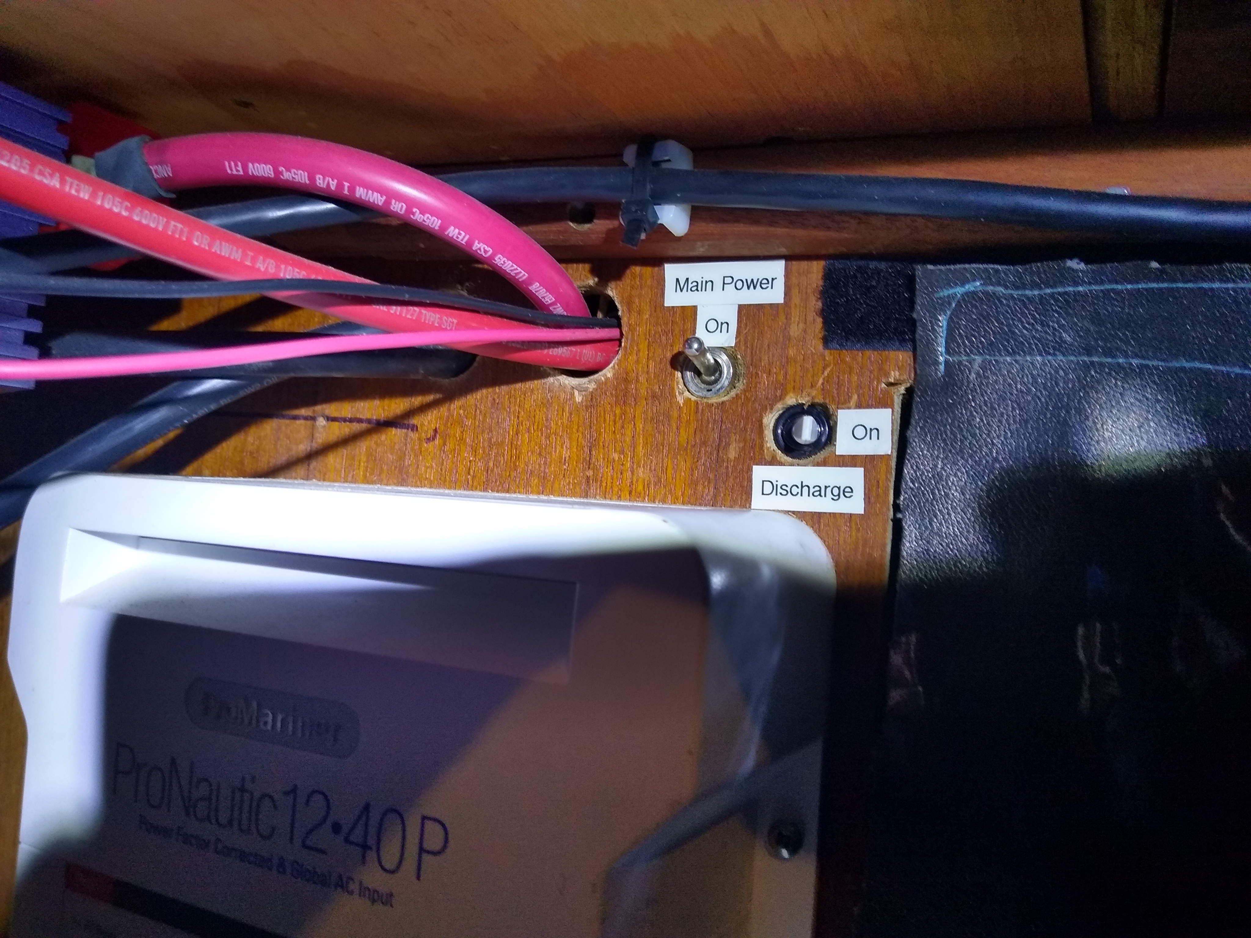
Anyway, even the soft reboot stopping working so that finally got me off my arse to fix it. I did so by adding in an additional switch. It’s in-between the P-Channel MOSFET (which takes the pulling-to-ground signal of the BMS and inverts it to +12v) and the 7713.
Now if I need to reset the system, I can just power off the system, power it back on, wait two seconds and then flip the discharge switch from on to off to on again. Simple.
Dear Matt,
SV Poppycock here again. I am the one that was designing a system exclusively with 7713 for cutoffs (remember, you were jealous of our high output alternator! 😉 ) . Thought I had things under control but didn’t fully understand the needed signal inversion. I know you use the MOSFET to do so but I’m a little confused (my knowledge of circuitry is limited but expanding quickly). I looked at the specs on the MOSFET you used but still I’m not quite clear. Could you explain a little more about what the mosfet is doing? Does the mosfet just invert the signal or does it also do the switching? Perhaps the most helpful thing would be drawing a quick schematic of its place in the system including the 7713 and the new switch you have added as well (artistic ability will not be judged!)
Poppycock will surely owe you many beers or spare parts in a distant anchorage!
Many thanks,
Nathaniel Montague
Hi, the 7713 requires a positive 12V signal while the BMS controls relays using a negative signal. All the MOSFET does is change then -12V to a +12V.
The additional switch is installed between the +12V supply and the source terminal on the MOSFET, it needs this as sometimes you need to be able to toggle the discharge bus off and on again to get into work after a system reset due to the 7713 logic
Stan Honey has a diagram up at http://honeynav.com/wp-content/uploads/2016/06/LFP-battery-Stan-Honey-notes.pdf
Thanks Matt; you are a legend. We are still stuck refitting in the Boston area of MA (should be setting sail for S. America in November). If you’re up this way and need anything at all, drop Poppycock a line. Another quick question as to the switch to get it to reset, does this mean that, in the event of a HVE, the discharge bus would not reset on it’s own if you were not on the boat?
Thanks! Heading across to french poly in a week or two so probably won’t cross paths for a while at least!
The HVE always resets successfully but if you turn off the BMS and turn it back on again, the 7713 won’t engage without that additional switch