OH GOD.
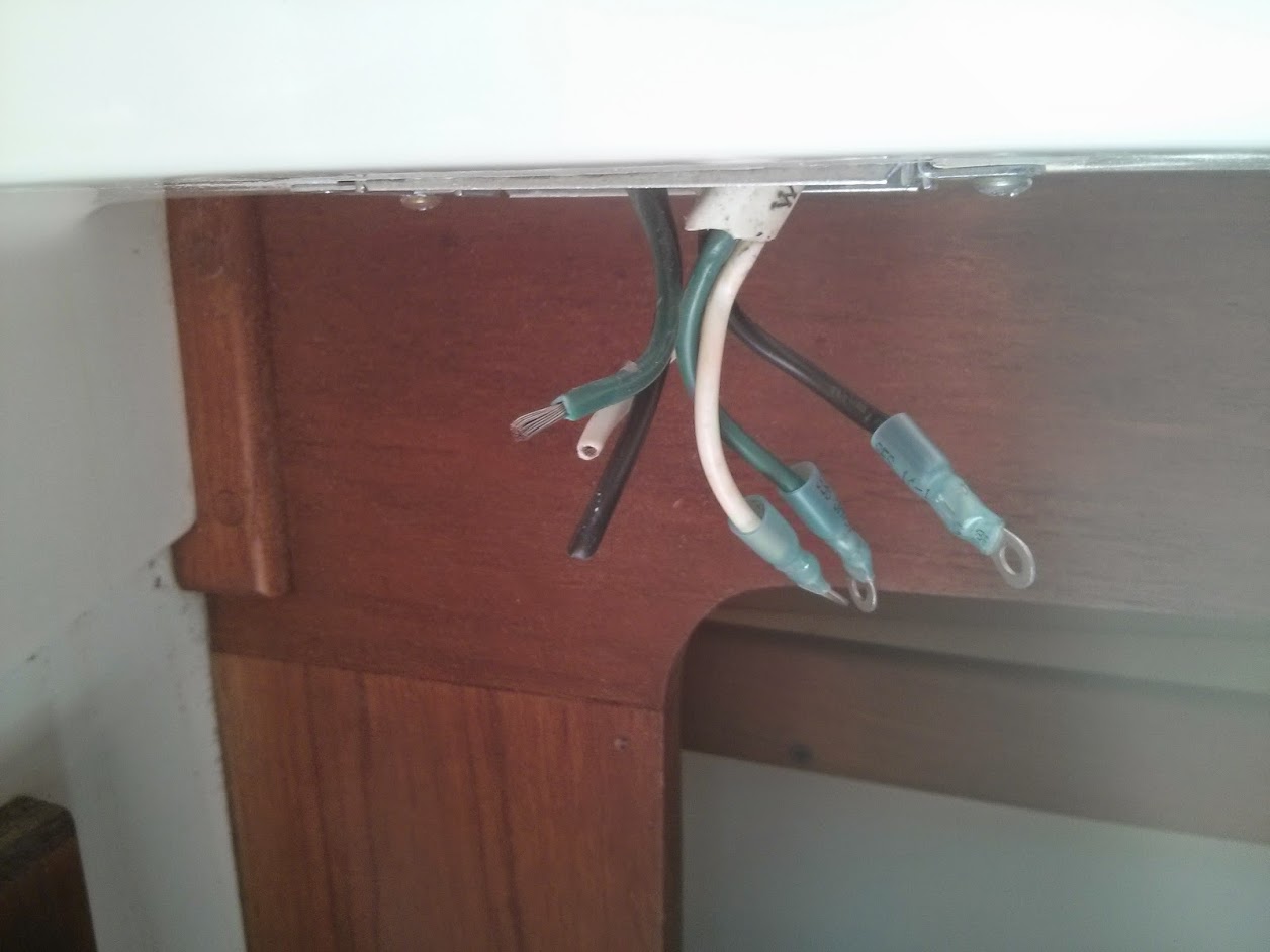
Anyway, first order of business was to add connectors onto the wires. In houses, this is done by just wrapping the wire strand around the screw. In boats, this doesn’t fly for a number of reasons.
I chose to use heat-shrink connectors, these are crimped on and then sealed using heat to make them waterproof.

So I started stripping the wires. After a bit of practice I got the right length, and started crimping on the connectors
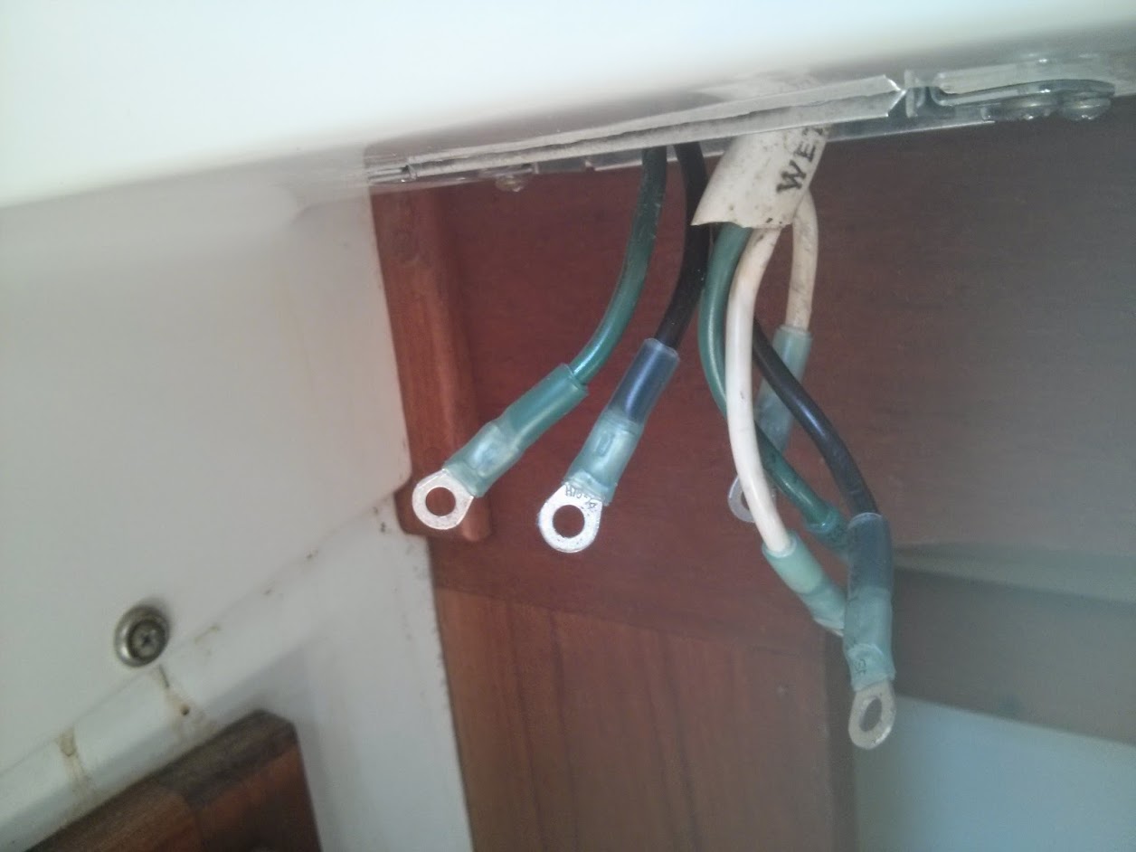
This is done by lining up all the strands of wire with the hole in the connector and then crimping it with a decent crimper.
Once all these were done, it was time to heat shrink them! Using my heat gun! That runs on AC Powoh shit.
After a couple of paniced minutes, I remmeber there was this weird 30->15 amp adapter plug thing that came with the boat. So I went and plugged in the 30amp shore power cable again, hooked up the adapter and presto! One AC outlet.
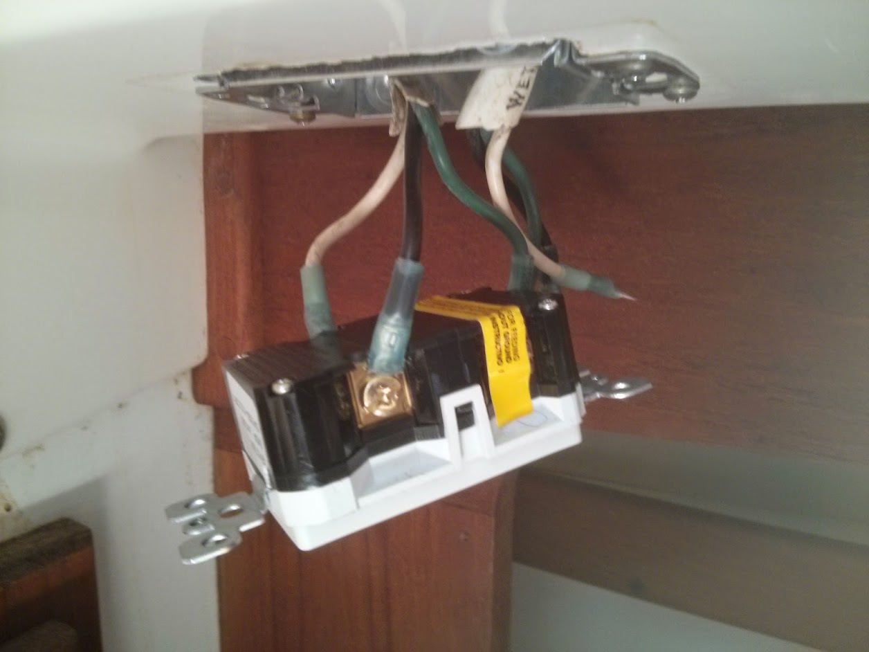
After heat shrinking, the wires looked like so
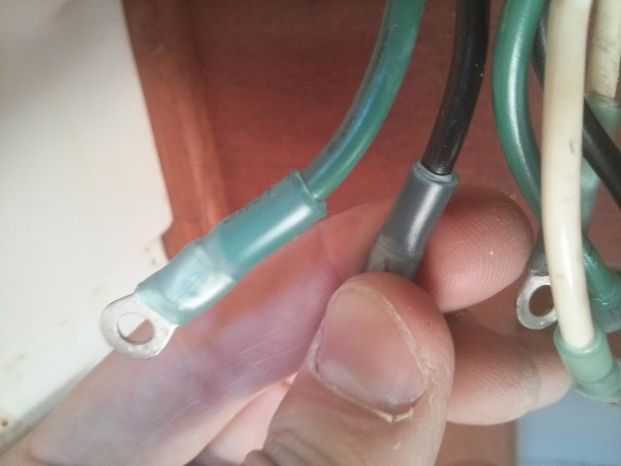
Nice and water tight!
I then removed the screws from the GFCI (they are not meant to be removed, but if you go slow and keep screwing they come out), slipped on the ring terminals – and found the connectors wouldn’t fit.
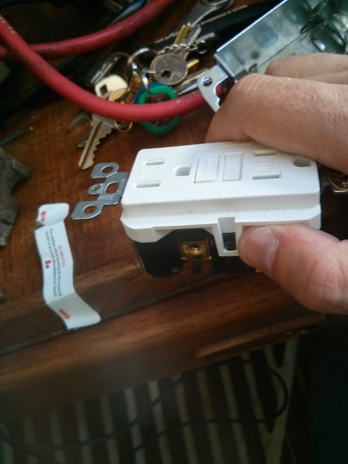
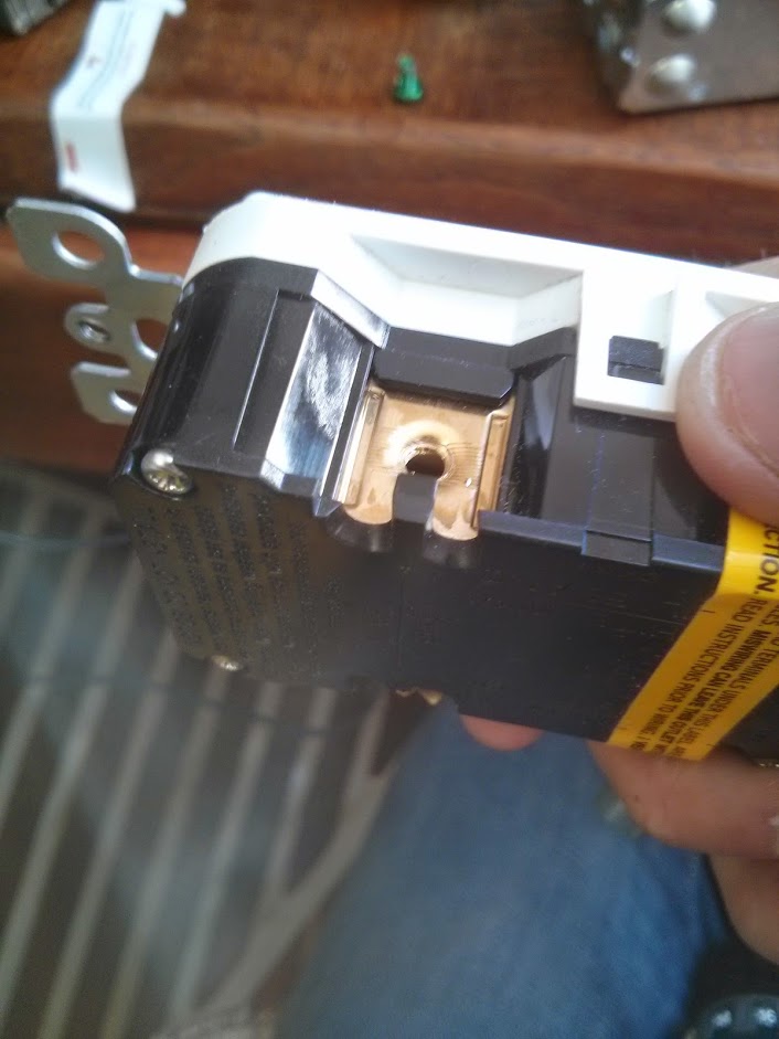
See that little black ridge on the underside of the screw hole? That was preventing the connectors from sitting. I snipped it off, sanded it down and managed to get all connectors on, after a couple of hours.
Then – disaster! No matter how much I pushed, it would not fit into the box! After mucking around for an hour I realised I was stuffed. I decided to see if I could get a bigger box – there was 2 inches of room in the compartment, and my box was 1 1/2, so if I could get a 2 inch one it may work. ARRRRRRRRRGH. I basically had to start from scratch again, thus making most of the previous two days completely wasted. ASHJDAKHJKDHSADKJAD
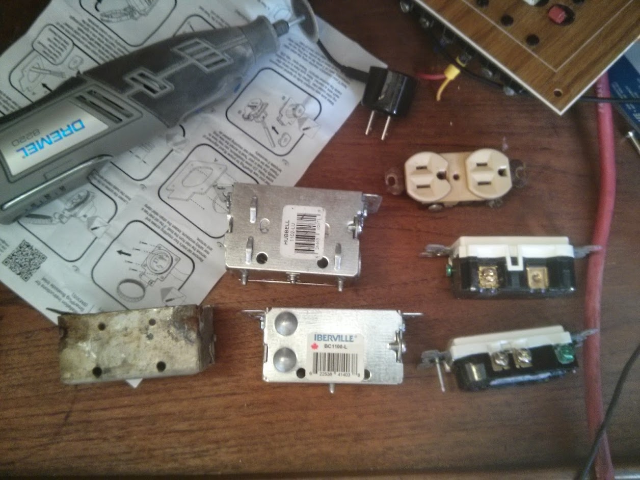
Here is a picture of the boxes.
On the left is the original box, top middle is the 2inch box I bought to replace the oriignal new box, shown bottom middle. On the right top is the old outlet, middle right is the GFCI, and bottom right is a new outlet I bought.
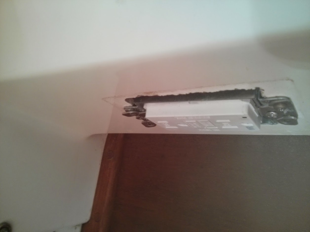
I took another half hour to get the old new box out of the hole, and then when I tried to put the new one in it wouldn’t fit! WHAT.
Turns out inside the hole where was a ‘knob’ of fiberglass where a join was. I had to sand it down using my dremel, and finally, FINALLY it fit in. That took another two hours.
Then I had to reconnect all the connectors again, taking another hour, and it finally went in.
Sadly, the screws that tighten the box to the wood are TOO BIG, so I have to switch them out, since the cover doesn’t fit on currently
But I’m 95% of the way! To… doing one of 7. That took 3 days.
I’ve had a think, and instead of replacing all the outlets with GCFIs, I’ll just replace the lead outlet on each circuit with one (which is actually what you are supposed to do, since GCFIs protect anything downstream, but I’d decided to put all GCFIs in anyway because Hey). The outlets I will use are a lot easier to install than the GCFIs because they are smaller, so hopefully the one remaining GFCI and 5 outlets won’t take nearly as long as this one.